Detailed Examples Of Shaft Machining Technology
| The formulation of the process specifications in the shaft parts is directly related to the quality of the workpiece, labor productivity and economic benefits. |
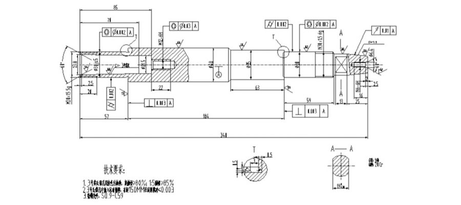
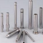
In response to the above requirements, the following is an example. A carburizing spindle (pictured above), 40 pieces per batch, material 20Cr, except for internal and external threads S0.9 ~ C59. The carburizing process is more complicated, and a sketch of the process must be drawn for the roughing process (pictured).
The formulation of the process specifications in the shaft parts is directly related to the quality of the workpiece, labor productivity and economic benefits.
A part can have several different processing methods, but only one of them is more reasonable. In the formulation of the machining process specification, the following points must be noted.
- 1.In the process analysis of the parts drawing, it is necessary to understand the technical requirements of the structural characteristics, precision, material, heat treatment, etc., and to study the product assembly drawing, component assembly drawing and acceptance criteria.
- 2.The processing route of carburizing parts is generally: cutting → forging → normalizing → roughing → semi-finishing → carburizing → carbon removal processing (for the part that does not need to improve hardness) → quenching → threading, drilling or milling Groove→rough grinding→low temperature aging→semi-finishing→low temperature aging→finishing.
- 3.Rough reference selection: If there is a non-machined surface, the non-machined surface should be selected as the rough reference. For casting axes that need to be machined on all surfaces, the minimum surface is corrected according to the machining allowance. And choose a smooth surface, let the gate. Select a solid and reliable surface as a rough reference, while the coarse reference is not reusable.
- 4.Fine benchmark selection: to meet the principle of baseline coincidence, as far as possible to select the design basis or assembly benchmark as the positioning benchmark. In line with the principle of benchmarking. Use the same positioning reference as much as possible in most operations. As much as possible, the positioning reference coincides with the measurement reference. The selection of high precision, stable and reliable surface is a fine benchmark.
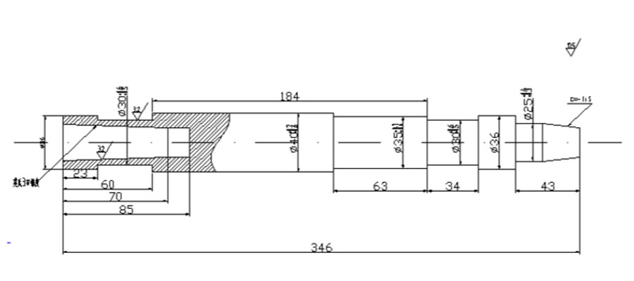
Spindle Machining Process
1.Turning
Process equipment: CA6140, Mohs No. 3 reamer, Mohs No. 3 plug gauge 1: 5 ring gauge
Process content: according to the process sketch turning all to size
- (1) The center hole φ2 is drilled at one end.
- (2) 1:5 taper and Mohs 3# inner cone color test, contact surface >60%.
- (3) The outer diameter of each outer circle to be grounded shall not exceed 0.1 in the radial run of the center hole.
Note: Finally check
2.Quenching
Process content: heat treatment S0.9-C59
3.Turned
Process content: deturningbonization. One end is clamped, one end is centered
- (1) The end face of the turning ensures that the length of the right end step of φ36 to the end of the shaft is 40
- (2) Drilling center hole φ5B type
- (3) U-turn
- (4) The end face of the turning, take a total length of 340 to the size, continue to drill deep to 85, 60 ° chamfer
4.Turning
Process equipment: CA6140
Process content: one clip and one top
- (1) Turning M30 × 1.5–6g left thread large diameter and ф30JS5 to Φ30+6.0 +5 .0++
- (2) Turning φ25 to φ25+0.2+0.1 length 43
- (3) Turning φ35 to φ353+0.4+0.3
- (4) Turning grinding wheel overpass
5.Turning
Process content: U-turn, one clip and one top
- (1) The large diameter of the M30×1.5–6g thread and the φ30JS5 to φ30+0.6+0.5
- (2) Turning φ40 to φ40+0.6+0.5
- (3) Turning grinding wheel overtravel slot
6.Milling
Process content: Milling 19+0.28 two planes to size
7.Heat treatment
Process content: heat treatment HRC59
8.Research
Process content: Grinding the two end center hole
9.External grinding
Process equipment: M1430A
Process content: two top tips, (the other end is blocked with a cone)
- (1) coarse grinding of φ40 outer circle, leaving 0.1 to 0.15 remaining
- (2) coarse grinding φ30js outer circle to φ30t+0.1+0.08 (two places) step grinding
- (3) Rough grinding 1:5 taper, leaving grinding allowance
10.Internal grinding
Process equipment: M1432A
Process content: use V-shaped fixture (positioning at the outer circle of ф30js5)
Momo’s 3# inner cone (re-matching Mohs 3# cone plug) finishing allowance 0.2~0.25
11.Heat treatment
Process content: low temperature aging treatment (baking), eliminating internal stress
12.Turning
Process equipment: Z-2027
Process content: clamped at one end and centered at one end
- (1) Drilling φ10.5 hole, positioning with guide sleeve, thread not attack
- (2) U-turn, drilling φ5 tap M6–6H internal thread
- (3) 60° center hole of the opening
- (4) Drill sleeve drill hole drilling ф10.5×25 (thread does not change)
- (5) 60° center hole, surface roughness 0.8
13.Pliers
Process content:
- (1) Insert the tapping machining bearing sleeve into the taper hole
- (2) Attack M12–6H internal thread to size
14.Research
Process content: Research center hole Ra0.8
15.External grinding
Process content: the workpiece is clamped between the two tops
- (1) Fine grinding φ40 and φ35φ25 outer circle to size
- (2) Milling M30×1.5 M30×1.5 left thread large diameter to 30-0.2-0.3-
- (3) Semi-finishing ф30js5 two to ф30+0.04+0.03
- (4) Fine grinding 1:5 taper to size, check by coloring method according to the touch surface is greater than 85%
16.Grinding
Process content: workpiece clamping two tops, grinding thread
- (1) Mill M30 × 1.5–6g left thread to size
- (2) Milling M30×1.5–6g thread to size
17.Research
Process content: Lapping center hole Ra0.4
18.External grinding
Process equipment: M1432A
Process content:
- (1) Fine grinding, workpiece clamping between two tops
- (2) Fine grinding 2-φ30-0.003-0.007 to size, pay attention to geometric tolerance
19. Internal grinding
Process equipment: MG1432A
Process content:
The workpiece is mounted in a V-shaped fixture, and the inner radius of Mohs 3 is fixed on the basis of 1–ф30 outer circle (unloading, positioning with 2–ф30js5 outer circle), and the coloring inspection contact surface is greater than 80%. Requires “1” and “2”
20.General
Process content: cleaning and coating anti-rust oil, vertical storage hanging into the workpiece
Some points in the machining of the shaft:
- 1.The two center holes are used as the positioning reference, which conforms to the aforementioned principle of reference coincidence and benchmarking.
- 2.The part first uses the outer circle as the rough reference, the end face of the car and the center hole of the drill, and then the outer circle of the rough car is positioned with the two center holes as the positioning reference, and the taper hole is processed with the outer circle of the rough car as the positioning reference, which is the principle of mutual reference. The machining has a positioning datum that is more accurate than once. No. 3 Mohs cone accuracy requirements are very high. Therefore, the V-shaped fixture is required to achieve the geometric tolerance requirement with the outer circle of 2-ф30js5 as the positioning reference. When the cone is inside the car, one end is clamped by a claw, and one end is centered on the center frame, and the outer circle is also used as a fine reference.
- 3.When semi-finishing and finishing the outer circle, a cone plug is used, and the center hole of the cone is used as a positioning reference for finishing the outer circular surface of the shaft.
For cone plugging requirements:
- 1.Cone plug has high precision, ensuring that the taper surface of the cone plug has a high degree of concentricity with its tip hole.
- 2.The cone plug should not be replaced after installation to reduce the installation error caused by repeated installation.
- 3.The external diameter of the outer diameter of the cone plug should be made near the end of the shaft to facilitate the removal and removal of the cone.
- 4.The main machining shaft is carburized and hardened with 20Cr low-carbon alloy steel, and the workpiece is not required to be hardened (M30×1.5-6g left, M30×1.5-6g, M12-6H, M6-6H), leaving 2.5-3mm carbon removal layer on the surface. .
- 5.After the thread is quenched, it cannot be processed on the lathe. If the thread is first screwed and then quenched, the thread will be deformed. Therefore, the thread generally does not allow hardening, so the carbon layer must be left in the diameter and length of the threaded portion in the workpiece. For internal threads, a 3 mm decarburization layer should also be left at the orifice.
- 6.In order to ensure the accuracy of the center hole, the center hole of the workpiece is also not allowed to be hardened. For this reason, the total length of the blank is 6 mm.
- 7.In order to ensure the grinding precision of the outer circle of the workpiece, the process of grinding the center hole must be arranged after the heat treatment, and a fine surface roughness is required. When the outer circle is ground, the roundness affecting the workpiece is mainly due to the coaxiality of the two top holes and the roundness error of the top hole.
- 8.In order to eliminate the grinding stress, a low temperature aging process (baking) is arranged after the rough grinding.
- 9.To obtain a high-precision outer circle, the grinding should be divided into rough grinding, semi-finishing, and fine grinding. Fine grinding is arranged on a high precision grinding machine.
Link to this article: Detailed Examples Of Shaft Machining Technology
Reprint Statement: If there are no special instructions, all articles on this site are original. Please indicate the source for reprinting:https://www.cncmachiningptj.com/,thanks!
 PTJ® provides a full range of Custom Precision cnc machining china services.ISO 9001:2015 &AS-9100 certified. 3, 4 and 5-axis rapid precision CNC machining services including milling, turning to customer specifications,Capable of metal & plastic machined parts with +/-0.005 mm tolerance.Secondary services include CNC and conventional grinding, drilling,die casting,sheet metal and stamping.Providing prototypes, full production runs, technical support and full inspection.Serves the automotive, aerospace, mold&fixture,led lighting,medical,bicycle, and consumer electronics industries. On-time delivery.Tell us a little about your project’s budget and expected delivery time. We will strategize with you to provide the most cost-effective services to help you reach your target,Welcome to Contact us ( [email protected] ) directly for your new project.
Link to this article:Detailed Examples Of Shaft Machining Technology
Reprint Statement: If there are no special instructions, all articles on this site are original. Please indicate the source for reprinting:Alloy Wiki,thanks!^^


