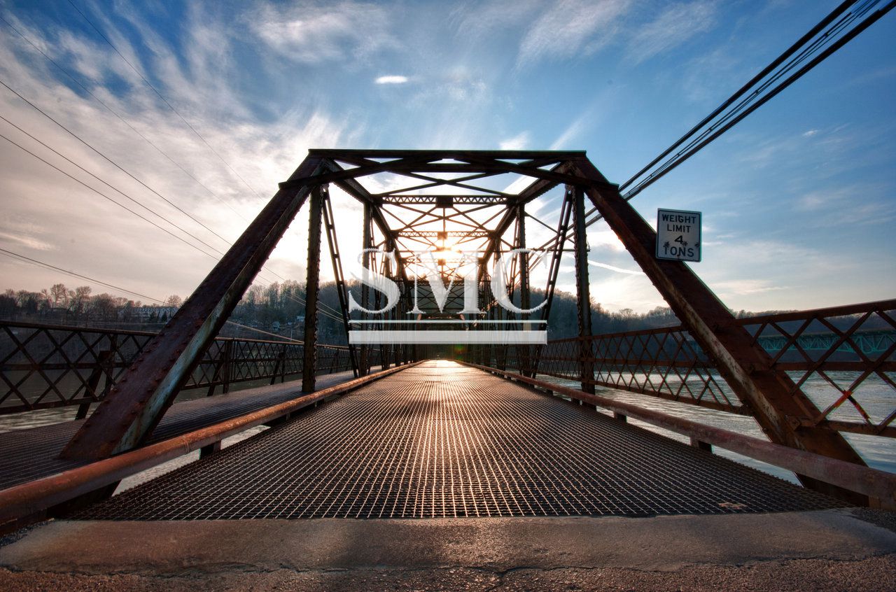
Footbridges are needed where a separate pathway has to be provided for people to cross traffic flows or some physical obstacle, such as a river. The loads they carry are, in relation to highway or railway bridges, quite modest, and in most circumstances a fairly light structure is required. They are, however, frequently required to give a long clear span, and stiffness then becomes an important consideration. The bridges are often very clearly on view to the public and therefore the appearance merits careful attention.
Steel offers economic and attractive forms of construction which suit all the requirements demanded of a footbridge.
Design
A fully detailed design can be prepared with other contract documents for pricing by tenderers. However, it is common practice, particularly for smaller bridges, for the detailed design of a footbridge to be included as part of a design and construct package. Many fabricators are able to provide such a package, using methods and details of construction developed to suit their particular fabrication facilities and expertise. However, the engineer supervising the work still needs to be acquainted with the different forms of construction which might be used and to be aware of their advantages and limitations.
Longer span bridges and those which form part of a larger scheme are likely to be designed in detail by a consultant or local authority. Within such an organization the engineer carrying out the design needs to be familiar with the particular requirements for footbridges, their features and construction details.
For the engineer in either of these situations, this article presents guidance on the conceptual design of steel and composite footbridges, to aid the selection of an outline design.

Features and forms of construction for footbridges
Footbridges, like any other bridge, must be long enough to clear the obstacle which is to be crossed and high enough not to interfere with whatever passes beneath the bridge. However, the access route onto the footbridge is often much different from what is familiar to the designer of a highway bridge: there is no necessity for a gentle horizontal alignment (indeed the preferred route may be sharply at right angles to the span). Structural continuity is therefore less common. The principal span is often a simply supported one.
Provision of suitable access for wheelchairs and cyclists is often specified for footbridges. Access ramps must be provided and restricted to a maximum gradient. The consequent length of ramps where access is from the level of the road or rail track over which the bridge spans is generally much longer than the bridge itself. The form of construction suitable for the ramps may have a dominant influence on the final form of the bridge.
The width of a footbridge is usually quite modest, just sufficient to permit free passage in both directions for pedestrians. Occasionally the bridge will have segregated provision for pedestrians and cyclists, in which case it will need to be wider. Parapets are provided for the safety of both the pedestrians and traffic flow. Footbridges over railway lines are required to have higher parapets and be provided with solid panels directly over the rail tracks.
Truss and Vierendeel girder beams
Trusses offer a light and economical form of construction, particularly when the span is large. The members of the truss can be quite slender and this naturally leads to the use of structural hollow sections. Hollow sections have been used for footbridges for over 50 years and some fabricators have specialised in this form of construction, developing techniques and details which utilize them to the best advantage.
Vierendeel girders using hollow section members offer an alternative but complementary structural form of similar proportion by substituting a rectangular form for the triangular arrangement used in trusses.
Trusses and Vierendeel girders are arranged with either half-through or through construction. Half-through construction is used for smaller spans, where the depth needed is relatively shallow. For larger spans, or where the truss is clad to provide a complete enclosure for the pedestrians, through trusses are used; the top chords are then braced together above head level.
Steel beam bridges
The simplest method of employing structural steel as the prime structural element of a footbridge is to use a pair of girders (fabricated or rolled sections), braced together for stability and acting as beams in bending, with a non-participating walkway surface on top. A typical small bridge deck might for example be formed by timbers placed transversely across the top of the beams. Precast slabs might also be used, without a shear connection to the steel and therefore not participating in global structural action.
Alternatively, the floor might be formed by steel plate, suitably stiffened to carry the pedestrian loads, in which case the plate could also be made to act structurally as the top flange of the steel beams
Steel box girder bridges
Another alternative is to use a small steel box girder. The top flange acts as the floor of the bridge, and there are usually short cantilevers either side of the box. This form has the benefits of good torsional stiffness, which can simplify support arrangements and clean surfaces which minimise maintenance.
Composite beam bridges
Composite beams, steel girders with a concrete slab acting as both a walkway floor and participating as a top flange, are a practical solution for medium span footbridges. They are a lighter version of the form of composite construction frequently employed in highway bridges. Slabs may be cast in situ, though the lesser requirements for the shear connection and the lighter design loads on the slab allow greater opportunity to employ precast slabs. The slab can also be cast on the beams in the works or other convenient site, since the weight and dimensions are often sufficiently modest to permit transport and erection of the complete superstructure.
Although composite construction is usually associated with I section girders, a concrete slab can also be used with a steel box girder.
Cable stayed bridges
In seeking to provide a bridge of light appearance, the use of cable stays is found to be very successful. It often affords scope to create a visually striking structure which provides a landmark or a focus for the area in which it is located. Almost any form of construction can be used with stays, though when a cable stayed form is chosen, the structural requirements are often found to be of secondary consideration to the achievement of a pleasing appearance.

Enclosed bridges
Enclosure of the sides of a footbridge is often called for to discourage the throwing of objects from the bridge. This is a particular requirement for bridges over railway lines. Full enclosure, to the sides and the roof of the walkway, is called for in situations where the users are to be protected from the environment and where greater protection is required over railway lines. Such enclosure justifies the use of through truss or Vierendeel construction. The form of construction will probably be dictated by consideration of appearance of the bridge and its relationship to adjacent structures. Whilst the general principles discussed in this guide are applicable, fully enclosed bridges are not specifically dealt with in detail here.
Shanghai Metal Corporation is a trusted aluminum alloy, aluminum foil price, stainless steel price and stainless steel manufacturer, kinds of stainless steel in china.
Guest contributors are welcome at the Alloy Wiki.It is a weekly wiki and guide on alloy information and processing technology, while also about the vast array of opportunities that are present in manufacturing. Our team of writers consists of a Machining Material Supplier / Machinist / Tool and Die Maker, a Biomedical Engineer / Product Development Engineer, a Job Development Coordinator / Adjunct Professor, and a President and CEO of a manufacturing facility.
Link to this article:Design of steel footbridges
Reprint Statement: If there are no special instructions, all articles on this site are original. Please indicate the source for reprinting:Alloy Wiki,thanks!^^


