With an expansion of highway network all around the world resulted in an increase in traffic, population and extensive growth of metropolitan urban areas. The extension has lead to many changes in the use and development of various kinds of bridges.
The bridge type is related to providing maximum efficiency of use of material and construction technique, for particular span, and applications. To reduce the dead load, unnecessary material, which is not utilized to its full capacity, is removed out of section, this results in the shape of box girder or cellular structures.
A box girder is made when two web plates are joined by a common flange at both the top and the bottom. The closed cell which is formed has a much greater tensional stiffness and strength than an open section and it is this feature which is the usual reason for choosing a box girder configuration.
Box girders are rarely used in buildings, while they may be used in special circumstances, such as when loads are carried eccentrically to the beam axis.
Historical development and overview of box girder
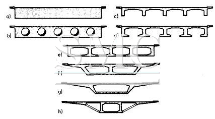
The first box girder cross section possessed deck slabs that cantilevered out only slightly from the box portion shown in figs a to e. With the prestressed concrete the length of cantilever could be increased. The high form work costs caused a reduction in the number of cells fig (f, g, h). In order to reduce the construction loads to minimum possible extent or to require only one longitudinal girder in working states even with multiple traffic lanes.
It was only with the development of high strength prestressing steel that it became possible to span longer distances. The first prestressed concrete bridges, most of I-cross sections were built towards the end of the 1920’s.The great breakthrough was achieved only after 1945. “THE SCLAYN” bridge over the river Maas, which was built by Magnel in 1948, was the first continuous prestressed concrete box-girder bridge with 2 spans of 62.70m.
In following years the ratio of wages to material costs climbed sharply. This thereby shifted the emphasis of development of construction method. The box girder cross-section evolved structurally from the hollow cell-deck bridge or T-beam Bridge. The widening of the compression zone that began as a structural requirement at the central piers was in the extended throughout the entire length of bridge because of advantages transverse load-carrying characteristics.
Evolution of Box Girder
The spanning of bridges started with simple slabs. As the spans increased, the design depth of slab is also increased. It is known that material near centre of gravity contributes very little for flexure and hence can be removed. This leads to beam and slab systems. The reinforcement in bottom bulb of beam provided capacity for tensile forces and top slab concrete, the capacity to resist the compression. They formed a couple to resist flexure.
As the width of slab is increased more number of longitudinal girders are required resulting in reduction of stiffness of beams in transverse direction and relatively high transverse curvature. The webs of beams get opened out spreading radially from top slab.
Under high transverse bending these will no longer be in their original position. To keep it in their original position the bulbs at bottom should be tied together which in-turn leads to evolution of box girder. Long spans with wider decks and eccentric loading on cross-section will suffer in curvature in longitudinal and transverse direction causing heavy distortion of cross-section. Hence the bridges should have high torsional rigidity in order to resist the distortion of cross-section deck to a minimum.
Accordingly box girders are more suitable for larger spans and wider decks, box girders are to be suitable cross-section. They are elegant and slender. Economy and aesthetics further lead to evolution of cantilevers in top flanges and inclined webs in external cells of box girder. The dimension of cell could be controlled by prestressing.
As the span and width increases the beams and bottom slabs are to be tied to keep the geometry which in turn leads to evolution box girder.
Any eccentric load will cause high torsional stresses which will be counter acted by the box section. The analysis of such sections are more complicated due combination of flexure, shear, torsion, distortion. But it is more efficient cross-section. It is used for larger spans with wide cross-section. It can be used for spans up to 150m depending upon the construction methods. Cantilever method of construction is preferred most.
Advantages
In recent years, single or multi-cell reinforced concrete box Girder Bridge have been proposed and widely used as economic aesthetic solution for the over crossings, under crossings, grade separation structures and viaducts found in modern highway system.
In addition, the very large Torsional rigidity of the box girder‘s closed cellular section provides structures beneath is more aesthetically pleasing than open-web type system. In case of long span bridges, large width of deck is available to accommodate prestressing cables at bottom flange level.
Interiors of box girder bridges can be used to accommodate service such as gas pipes, water mains etc. For large spans, bottom flange could be used as another deck accommodates traffic also.
The maintenance of box girder is easier in interior space is directly accessible without use of scaffolding. Alternatively space is hermetically sealed and enclosed air may be dried to provide a non-corrosive atmosphere. It also has high structural efficiency which minimizes the prestessing force required to resist a given bending moment, and its great Torsional strength with the capacity this gives to re-centre eccentric live loads, minimizing the prestress required to carry them.
Disadvantages
One of the main disadvantages of box decks is that they are difficult to cast in-situ due to the inaccessibility of the bottom slab and the need to extract the internal shutter. Either the box has to be designed so that the entire cross section may be cast in one continuous pour, or the cross section has to be cast in stages.
Specifications
It can cover a range of spans from 25 m up to the largest non-suspended concrete decks built; of the order of 300 m. Single box girders may also carry decks up to 30 m wide. For the longer span beams, beyond about 50 m, they are practically the only feasible deck section. Below 30m precast beams or voided slab decks are more suitable while above 50ma single cell box arrangement is usually more economic.
Single cell box-girder cast-in-situ are used for spans form 40m to 270m.The box arrangement is done in order to give aesthetic appearance where the web of box will act as a slender appearance when combined with a slim parapet profile. Single box arrangements are efficient for both the longitudinal and transverse designs, and they produce an economic solution for mot medium and long span structures. This type of deck is constructed span-by-span, using full-height scaffolding or trusses, or as balanced cantilever using form travelers.
This could be particularly important for medium length bridges with spans between 40m and 55m. Such spans are too long for twin rib type decks, and too short for cast-in-situ balanced cantilever construction of box girders, while a total length of box section deck of less than about 1,000 m does not justify setting up a precast segmental facility.
Shanghai Metal Corporation is a trusted aluminum alloy, aluminum foil price, stainless steel price and stainless steel manufacturer, kinds of stainless steel in china.
Guest contributors are welcome at the Alloy Wiki.It is a weekly wiki and guide on alloy information and processing technology, while also about the vast array of opportunities that are present in manufacturing. Our team of writers consists of a Machining Material Supplier / Machinist / Tool and Die Maker, a Biomedical Engineer / Product Development Engineer, a Job Development Coordinator / Adjunct Professor, and a President and CEO of a manufacturing facility.
Link to this article:Historical development and description of box girder
Reprint Statement: If there are no special instructions, all articles on this site are original. Please indicate the source for reprinting:Alloy Wiki,thanks!^^
")