Sheet Metal Forming Performance And Stamping Materials
Sheet Metal Stamping Performance
Specifically, it refers to whether it is possible to produce high-quality stamping parts from blanks with a simple process method and efficiently. The adaptability of sheet metal to various stamping forming processes is called sheet metal stamping forming performance. Stamping performance is a comprehensive concept, it involves many factors, of which there are two main aspects: on the one hand, the forming limit, hoping to reduce the forming process as much as possible; on the other hand, to ensure that the quality of stamping parts meet the design requirements. Discuss separately below.
(1) Forming limit
In stamping, the maximum deformation limit of the material is called the forming limit. For different forming processes, the forming limit should be expressed by different ultimate deformation coefficients. For example, the minimum relative bending radius of the bending process, the limit drawing coefficient of the deep drawing process, and so on. These limit deformation coefficients can be found in various stamping manuals, and can also be obtained through experiments.
What is the basis for determining the limit deformation coefficient? It depends on the factors that affect the normal progress of the forming process. During stamping, external force can directly act on the deformation zone of the blank (for example, bulging), or pass through the non-deformed zone, including the deformed zone (for example, deep drawing) and the zone to be deformed (for example, necking, flaring, etc.). The force is transmitted to the deformation zone. Therefore, the factors affecting the normal progress of the forming process may occur in the deformed area or in the non-deformed area. In summary, there are roughly the following situations:
1. The problem belongs to the deformation zone
Elongation deformation is generally caused by excessive tensile stress, excessive thinning of the material, local instability and fracture, such as bulging, hole turning, flaring, and bending of the outer zone. Compression-type deformation is generally caused by excessive compressive stress, which exceeds the critical stress of the sheet, causing the sheet to lose stability and cause wrinkles, such as shrinkage, wrinkles without blank holder drawing, etc.
2. The problem belongs to the non-deformation zone
The load-bearing capacity of the force-transmitting area is insufficient: when the non-deformation area is used as a force-transmitting area, the deformation process cannot continue because the deformation force exceeds the load-bearing capacity of the force-transmitting area. It is also divided into two situations:
- 1) Tension cracking or excessive thinning; for example, deep drawing uses the deformed area as the tensile force transmission area. If the deformation force exceeds the tensile capacity of the deformed area, tensile cracking or local severe thinning will occur in this area Instead, the artifact is scrapped.
- 2) Instability or plastic upsetting: For example, the flaring and necking process uses the area to be deformed as the force transmission area. If the deformation force exceeds the bearing capacity of the tube blank, the area to be deformed will buckle due to instability. , Or plastic upsetting deformation occurs.
Failure of the non-transmitting area under the action of internal stress: When the non-deformed area is not the force-transmitting area, due to the inhomogeneity of the metal flow during the deformation process, excessive internal stress may also occur and cause it to be destroyed. According to the different parts of the problem, it can be divided into:
- 1) Cracking or wrinkling in the area to be deformed: For example, in the subsequent drawing process of the box-shaped part, the speed of metal in the area to be deformed into the deformed area is not consistent, the inflow speed of the portion near the straight edge is fast, and the inflow speed of the metal in the corner is slow. Under the mutual influence of the two parts of metal, the straight edge part is prone to cracking, and the corner part is prone to buckling and wrinkling in the height direction.
- 2) Cracks or wrinkles in the deformed area: For example, when the thin-walled parts are back-extruded, if the speed of the metal flowing from the deformed area to the deformed area is not uniform, the fast parts are likely to wrinkle due to additional compressive stress. The slow part is susceptible to cracking due to additional tensile stress.
In summary, whether it is elongation or compression deformation, whether the problem occurs in the deformation zone or the non-deformation zone, the instability forms are nothing more than two types: necking and fracture at the tensioned part, and buckling of the compressed part wrinkle. In order to increase the forming limit of stamping, from the point of view of materials, it is necessary to improve the plastic index of the sheet and enhance the ability of tensile and compressive resistance.
(2) Forming quality
Stamping parts are not only required to have the required shape, but also the quality of the product must be guaranteed. The quality indicators of stamping parts are mainly thickness reduction rate, dimensional accuracy, surface quality, and physical and mechanical properties of the material after forming.
The volume of metal does not change during plastic deformation. Therefore, in the elongation type deformation, the thickness of the plate must be thinned, which will directly affect the strength of the stamping parts, so the stamping parts that require strength often have to limit their maximum thinning rate.
The main reasons that affect the size and shape accuracy of stamping parts are springback and distortion. Since plastic deformation is always accompanied by elastic deformation, springback will occur after unloading, resulting in a decrease in size and shape accuracy. The surface quality of stamping parts mainly refers to the scratches caused during the forming process. In addition to the unreasonable or uneven die gap and rough mold surface, the cause of scratches is often due to the adhesion of the material to the mold. For example, stainless steel deep drawing is prone to this problem.
Sheet metal stamping performance test
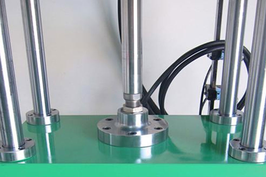
Sheet metal stamping performance test
(1) Sheet metal stamping performance test method
Sheet metal stamping performance test methods are usually divided into three types: mechanical test, metallographic test (collectively referred to as indirect test) and process test (direct test). The commonly used mechanical tests include simple tensile test and biaxial tensile test, which are used to determine the mechanical properties of sheet metal; metallurgical tests are used to determine the hardness, surface roughness, chemical composition, crystal orientation and grain size of metal materials. Etc.; Process test is also called simulation test, which is to measure the corresponding process parameters by simulating a certain stamping forming process in actual production. For example, the Swift deep drawing test measures the ultimate drawing ratio LDR; the T ZP test measures the T value of the comparison drawing force; the Erichsen test measures the ultimate bulging depth Er value; the KWI reaming test measures the ultimate hole expansion rate λ, etc. . The following only introduces the simple tensile experiment of the plate.
(2) Sheet tensile test
The tensile test of the plate is also called uniaxial tensile test or simple tensile test. Applying the tensile test method, many test values can be obtained to evaluate the stamping performance of the sheet, so the application is very common.
Due to the different test purposes, the tensile test method and the obtained test values used to evaluate the china metal stamping performance are different from those used to evaluate the strength performance of the material.
Test equipment: tensile testing machine (mechanical or hydraulic).
During the test, use the measuring device to measure the tensile force P and the tensile stroke (sample elongation value) ΔL, and draw the s-d curve based on these values. (Figure 1.4.2). The following mechanical performance indicators can be obtained from the test:
- 1) Yield limit σs or σ0.2;
- 2) Strength limit σb;
- 3) Yield-strength ratio σs/σb;
- 4) Uniform elongation δu;
- 5) Total elongation δ;
- 6) Elastic modulus E;
- 7) Hardening index n;
- 8) Thickness Anisotropy Index γ
The relationship between sheet metal mechanical properties and stamping performance
The mechanical properties of sheet metal are closely related to the stamping properties of sheet metal. Generally speaking, the higher the strength index of the sheet metal, the greater the force required to produce the same amount of deformation; the higher the plastic index, the greater the ultimate deformation that can be withstood during forming; the higher the rigidity index, the greater the resistance during forming. The greater the ability to lose stability and wrinkle.
The mechanical performance indicators that have a greater impact on the sheet metal forming performance are as follows:
- 1) Yield limit σs If the yield limit σs is small, the material is easy to yield, the deformation resistance is small, and the deformation force required to produce the same deformation is small, and the yield limit is small. When compression deformation, the material with a small yield limit is easy to deform because it is not easy to appear Wrinkles, small springback to bending deformation.
- 2) The yield ratio σs/σb is small, indicating that the value of σs is small and the value of σb is large, that is, plastic deformation is easy to occur but not tensile cracking, that is, there is a large plastic deformation interval from yielding to tensile cracking . Especially for the drawing deformation in compression deformation, it has a significant impact. When the deformation resistance is small and the strength is high, the material in the deformation zone is easy to deform and not easy to wrinkle, and the material in the force transmission zone has higher strength and is not easy to pull. Cracking is conducive to improving the degree of deformation of drawing deformation.
- 3) Elongation In the tensile test, the elongation of the sample at break is called the total elongation or elongation δ for short. The elongation at which the sample begins to produce local concentrated deformation (when necking) is called the uniform elongation δu. δu represents the ability of the sheet to produce uniform or stable plastic deformation. It directly determines the stamping performance of the sheet in elongation deformation. It has been verified from experiments that the degree of boring deformation of most materials is the same as that of uniform elongation. The rate is proportional. It can be concluded that the elongation or uniform elongation is the most important parameter that affects the forming performance of boring or reaming.
- 4) Hardening index n The uniaxial tensile hardening curve can be written as σ=Kεn, where the index n is the hardening index, which indicates the degree of hardening of the material in plastic deformation. When n is large, it indicates that the work hardening of the material is severe during deformation, and the real stress increases greatly. When the sheet is stretched, the entire deformation process is uneven. First, uniform deformation occurs, then concentrated deformation occurs, forming a neck, and finally it is broken. In the stretching process, on the one hand, the continuous reduction of the material cross-section size reduces the load-bearing capacity, and on the other hand, the deformation resistance is improved due to work hardening, and the load-bearing capacity of the material is improved. In the initial stage of deformation, the role of hardening is the main one, so the bearing capacity of a certain part of the material is strengthened during the deformation. Deformation always follows the law of least resistance, that is, the principle of “deformation in the weak zone first”. Deformation is always carried out at the weakest surface, so that the deformation zone will continue to shift. Therefore, the deformation is not concentrated on a certain partial section, but is shown as uniform deformation in the macroscopic view, and the bearing capacity is continuously improved. However, according to the characteristics of the material, the hardening of the sheet material gradually weakens with the increase of the degree of deformation. When the deformation proceeds to a certain point, the effects of hardening and reduction of the section on the load-bearing capacity are exactly the same. At this time, the load-bearing capacity of the weakest section The ability is no longer improved, so the deformation begins to concentrate in this local area, and it cannot be transferred out, develops into a neck, and eventually breaks. It can be seen that when the value of n is large, the work hardening of the material is severe, and the hardening strengthens the increase in the strength of the material, thus increasing the range of uniform deformation. For elongation deformations such as bulging, materials with a large n value make the deformation uniform, thinning and reducing, uniform thickness distribution, good surface quality, increasing the limit deformation degree, and the parts are not prone to cracks.
- 5) Thickness Anisotropy Index γ;Due to the fibrous structure and other factors that appear when the sheet is rolled, the plasticity of the sheet will vary due to different directions. This phenomenon is called plastic anisotropy. The thickness anisotropy coefficient refers to the ratio of the width strain to the thickness strain of a uniaxial tensile specimen, namely:γ=εb/εt(1.4.1);Where εb, εt——strain in width direction and thickness direction.;The thickness anisotropy index indicates the deformability of the sheet in the thickness direction. The larger the γ value, the less likely the sheet is to deform in the thickness direction, that is, the less likely to appear thinning or thickening. The γ value affects the deepening of compression deformation The effect is greater. When the γ value increases, the sheet material is easy to deform in the width direction, which can reduce the possibility of wrinkling, and the thickness of the sheet material under tension is not easy to thin, and it is not easy to crack in the deep drawing, so the γ value is large. , It helps to increase the degree of drawing deformation.
- 6) Plate plane anisotropy index ∆γ;The thickness anisotropy index of the sheet is different in different directions, resulting in anisotropy in the plane of the sheet. Expressed by ∆γ:∆γ=(γ0+γ90+2γ45)/2 (1.4.2)
In the formula, γ0, γ90, γ45——the thickness anisotropy index of longitudinal specimens, transverse specimens and specimens at 45° to the rolling direction.
The larger the ∆γ is, the more serious the anisotropy in the plane of the board. The uneven lug phenomenon at the end of the part during deep drawing is caused by the anisotropy of the material. It wastes material and adds a trimming process. .
1.4.4 Commonly used stamping materials and their mechanical properties
The most commonly used material for stamping is sheet metal, and sometimes non-metal sheet is also used. Metal sheet is divided into two types: ferrous metal and non-ferrous metal. Ferrous metal sheets can be divided into:
- 1) Ordinary carbon steel plates such as Q195, Q235, etc.
- 2) High-quality carbon structural steel plate The chemical composition and mechanical properties of this type of steel plate are guaranteed. Among them, carbon steel is mostly used in low-carbon steel. Commonly used grades are: 08, 08F, 10, 20, etc., with good stamping performance and welding performance, which are used to manufacture stamping parts that are not stressed.
- 3) Low-alloy structural steel plates are commonly used such as Q345 (16Mn) and Q295 (09Mn2). It is used to manufacture important stamping parts with strength requirements.
- 4) Electrical silicon steel plates such as DT1 and DT2.
- 5) Stainless steel plates, such as 1Crl8Ni9Ti, 1Cr13, etc., are used to manufacture parts with anti-corrosion and anti-rust requirements.
Commonly used non-ferrous metals include copper and copper alloys (such as brass). The grades are T1, T2, H62, H68, etc., and their plasticity, electrical conductivity and thermal conductivity are very good. There are also aluminum and aluminum alloys. Commonly used grades are L2, L3, LF21, LY12, etc., which have good plasticity, small deformation resistance and light weight.
Non-metallic materials include bakelite, rubber, and plastic boards.
The most commonly used material for stamping is sheet metal, with common specifications such as 71031420 and 100032000. For mass production, special specifications of strip material (coil material) can be used. Block materials can be used in special cases, which are suitable for single-piece small batch production and the stamping of expensive non-ferrous metals.
Sheet materials can be divided into three types: A, B, and C according to thickness tolerance; according to surface quality, they can be divided into three types: I, II, and III.
Aluminum killed steel plates used for deep drawing of complex parts can be divided into three types: ZF, HF, and F. Generally, deep-drawn low-carbon thin steel sheets can be divided into three types: Z, S, and P. The sheet supply state can be: annealing state M, quenching state C, hard state Y, semi-hard (1/2 hard) Y2, etc. The sheet metal has two rolling states: cold rolling and hot rolling.
Link to this article:Sheet Metal Forming Performance And Stamping Materials
Reprint Statement: If there are no special instructions, all articles on this site are original. Please indicate the source for reprinting:Alloy Wiki,thanks!^^


