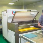
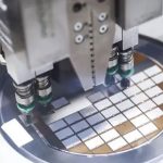
Melt extrusion (FDM) 3D printers usually use thermoplastics as materials, such as ABS, PLA, nylon and other plastics as 3D printing materials. This type of printer is also widely used because of its low price, so it is also called a desktop printer. The filamentous material is heated to a molten state in the printing nozzle during printing. The printing nozzle moves along the filling trajectory of the cross-sectional contour line of the object model after layering and slicing, and at the same time ejects the molten material to make it adhere to the object model. After that, the material quickly cools and solidifies, and merges with the model below to form the final shape. The printer is on the printing base, starting from the bottom of the model, and printing layer by layer from bottom to top to the top.
Due to the principle of stacking molten materials layer by layer in the FDM type 3D printing process, when printing the suspended parts of the object model, the extruded plastic filaments hang in the air and cannot be fused with the model. Therefore, it is necessary to detect the suspended part of the object model before generating the print trajectory, and add an appropriate support structure below. The added support structure is used as part of the object model during the 3D printing process.
In this way, the plastic filament can be effectively combined with the supporting structure below when printing the original suspended part. Poorly designed support structures will increase a lot of material loss and need to be artificially peeled off after printing, which may also cause damage to the surface of the object model. Therefore, when designing the support structure, the total volume of the support structure and the area in contact with the surface of the object model should be minimized under the premise of ensuring the printability of the object model.
How to design a reasonable support structure is an important issue that 3D printing equipment using FDM 3D PRINTING technology needs to face. The algorithm for generating the support structure should be optimized for material saving under the premise of ensuring the printability of the object model. So it can be summarized into two main problems:
- (1) How to find the parts that need to be added support?
- (2) How to generate the supporting structure?
For the first question, the key is to ensure that all areas that need to be supported in the object model can be detected. For the second problem, the generated support structure should ensure that it can provide effective support for the object model. In addition, the support structure should be easier to remove after successful printing, thereby reducing damage to the surface of the object model.
There are many ways to deal with these two problems. In terms of finding the area to be supported, the commonly used method is to select all surfaces in the three-dimensional object model that face downward and have a small angle with the horizontal plane as the parts that need to be supported. Many existing slicing engines such as Ultimater’s Cura, Autodesk’s MeshMixer, etc. all use this 3D Printing method. Another method is to make a Boolean difference between two consecutive slice layers.
Eggers and Renap selected a subset by downsampling. In terms of adding a support structure, one approach is to create a pole-like support that is connected to the printing base or the model itself under the surface that needs to be supported. Another method is to generate tree-like structure support under the surface to be supported. Currently, MeshMixer and Vanek have used this method. The algorithm in this paper deals with the problem of adding support based on the improvement of the tree support method.
The input of the tree support is a set of points representing its leaf nodes. Therefore, to add support to the triangular facets and edges, it is necessary to convert them into point sets. Take the triangular patch as an example, the transformation method is to project it onto the plane of the printing base, and sample it uniformly through the scan line algorithm. After acquiring the sampling points on the plane of the printing abutment, they are mapped back to the original patch respectively. The mapping method is to make a ray from the sampling point and the printing direction, and the intersection point with the original patch is the final support point. The sampling accuracy is related to the minimum printable accuracy of the printer. According to experience, twice the minimum printable accuracy is used as the sampling interval.
Link to this article:Material saving optimization algorithm based on improved 3D printing tree support structure
Reprint Statement: If there are no special instructions, all articles on this site are original. Please indicate the source for reprinting:Alloy Wiki,thanks!^^


